Mold Ejector Setup: Part 2 - Using part ejection on a manual bench top molding machine


In part 1 of this series, we showed the process of adding ejector pins to a prototype injection mold using a Syncorda Protoframe mold frame with ejection. In this part, we will show the mold being used to make parts on a Buster Beagle 3D MK3 bench top injection molding machine.
Step 1 - Setup
The B/core side of the mold was already be set up in part 1. Next, we install the A/cavity side of the mold in the mold frame. When using resin 3D printed mold inserts, we get the best results when the insert is very slightly above or “proud” of the mold frame. This causes the insert to compress a bit when the mold is clamped shut, and reduces mold flash. When necessary, we add a paper shim behind the mold insert to achieve this. The insert is just high enough to feel the height difference with a finger. When using metal inserts, having the insert flush with the edge of the frame is preferable.
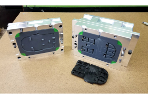
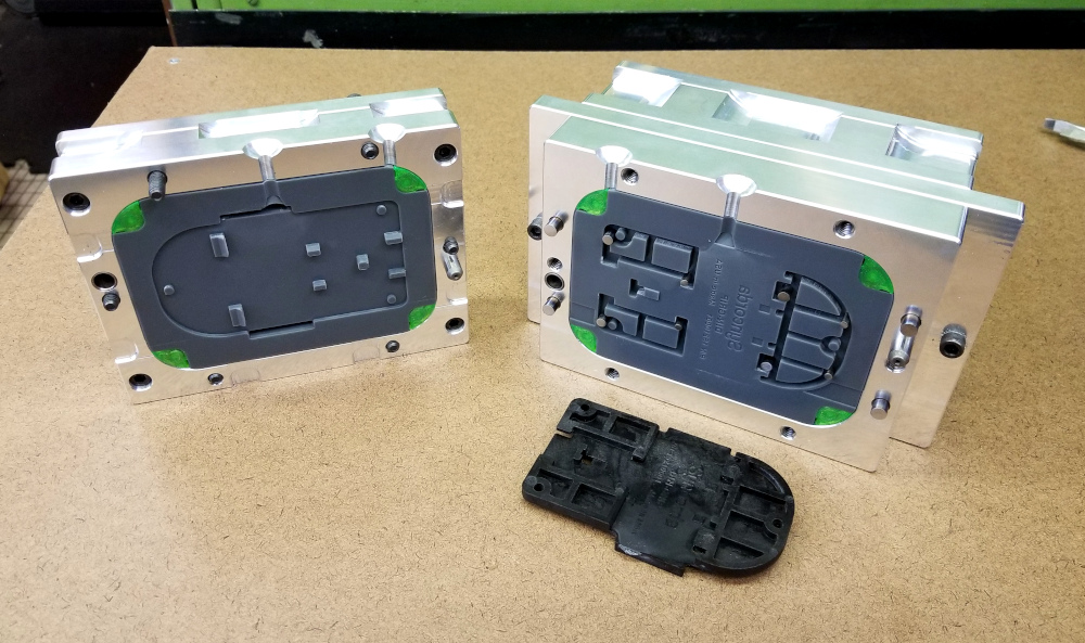
Below, the two halves of the mold are shown ready to use. We have also installed insert bolt head covers (green) so that if we use too much injection pressure and get significant mold flash, we can still get the bolts out.
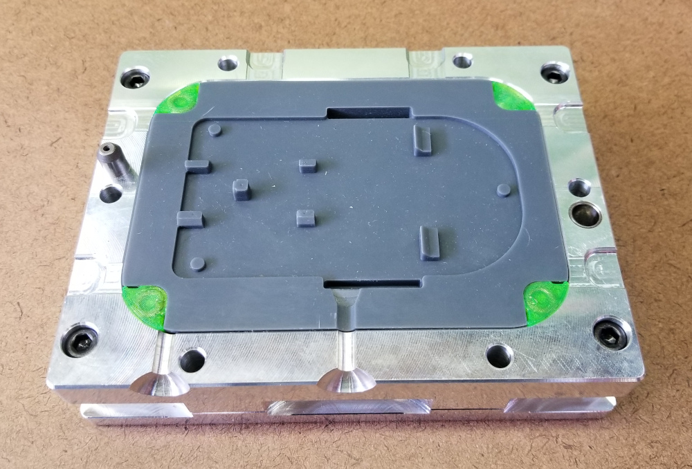
Figure 1 - The assembled cavity (A) side of mold
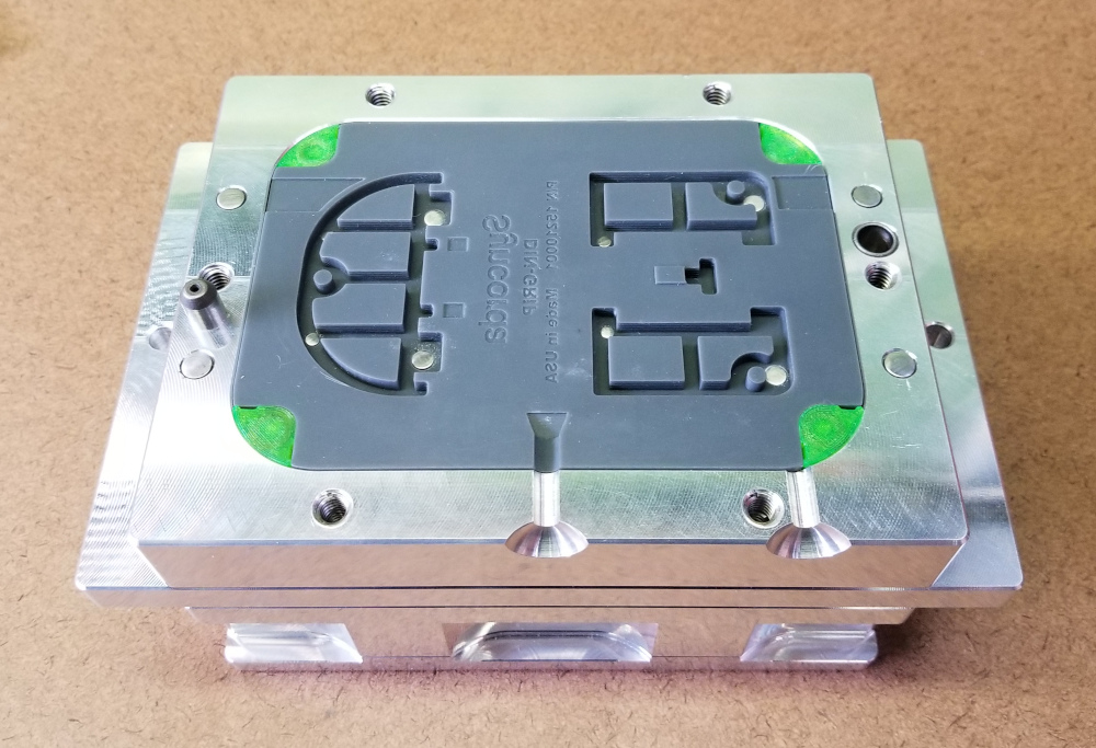
Figure 2 - The assembled core (B) side of mold
Step 2 - Assembling Mold Halves
Before putting the two halves of the mold together, we spray release agent on each side. We are using a food grade silicone release agent, although there are probably non food-safe formulations that would provide better release.
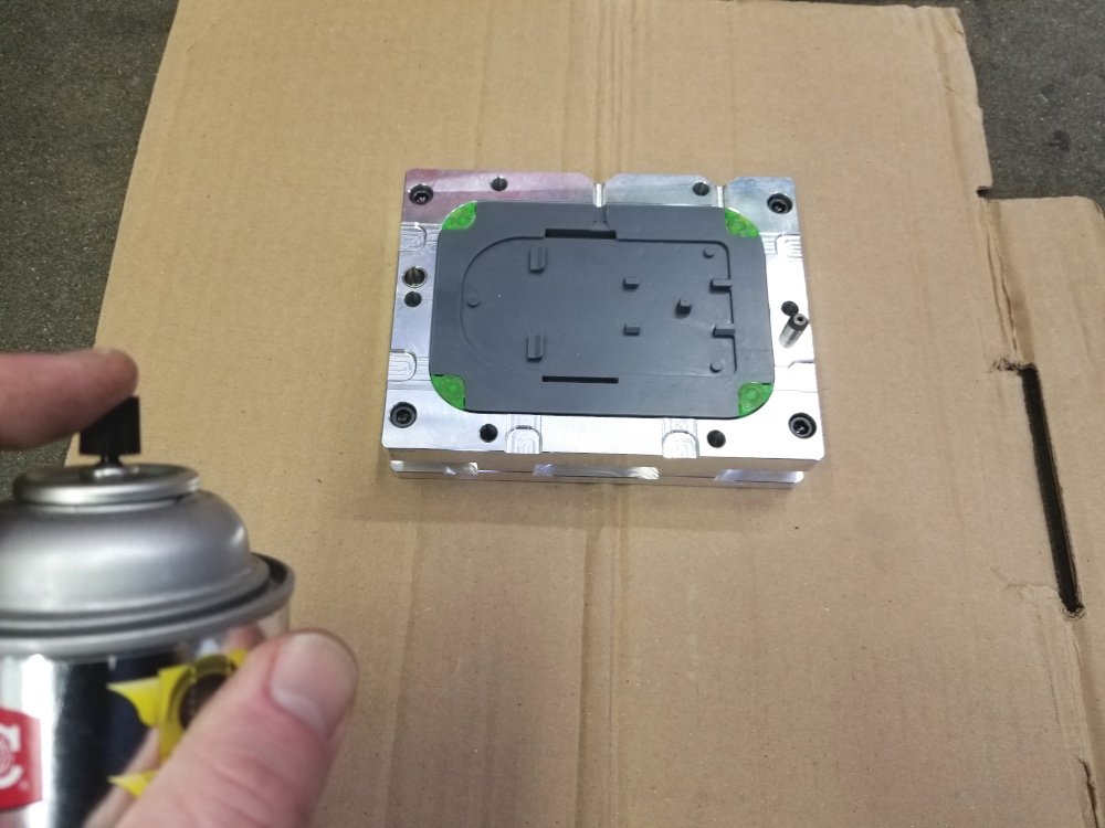
Figure 3 - Apply release agent
The ejector plate is pushed back so it is touching the bottom clamp plate to retract ejector pins. This mold frame has return pins that will automatically push the plate back when the mold is closed, but it is easier to assemble with the pins retracted.
Next, we slide the mold halves together. The alignment pins are a tight fit and can bind, so we find that it helps to set both halves of the mold upright on a flat surface and carefully slide them together. The mold halves must remain parallel, otherwise the alignment pins will bind.
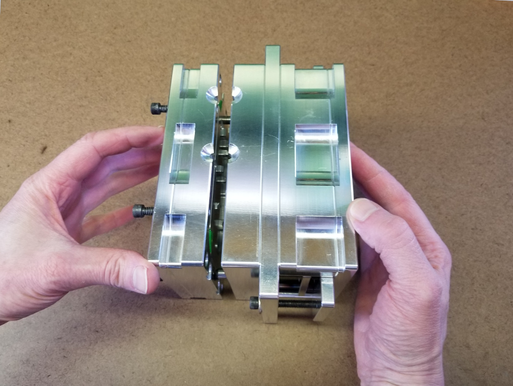
Figure 4 - Sliding mold halves together
Our mold has a large surface area that pushes the limits of this machine. We are using the perimeter clamping bolts of the mold frame to get more clamping force than the small vise in the Buster Beagle could provide.
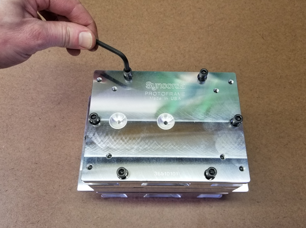
Figure 5 - Tightening clamping bolts
Step 3 - Injecting Plastic
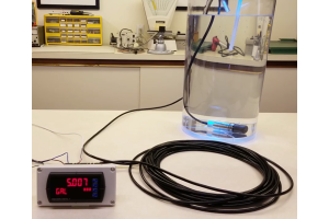
We add plastic pellets and allow the barrel to heat to temperature.
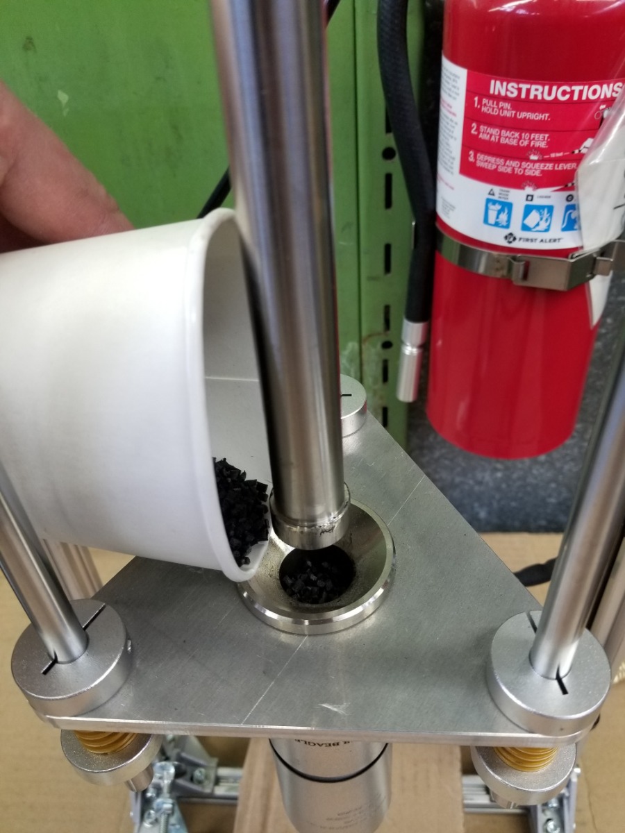
Figure 6 - Adding plastic pellets
The mold is then loaded in the machine. If we were using a clamp in our machine, we would engage it now, but here we are just using the bolts in the mold frame.
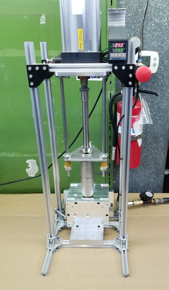
Figure 7 - The mold loaded in the machine
Before injecting, we check that the injection pressure is in the proper range. On the Buster Beagle it is set by adjusting an air pressure regulator. It is better to start low and risk a short shot than to start too high and have the mold flash badly.
Time to give it a shot!
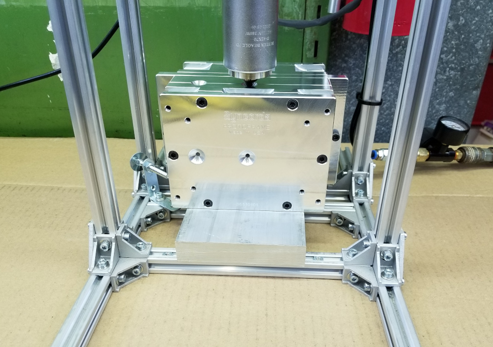
Figure 8 - The mold ready to inject
Step 4 - Opening the Mold
After the plastic is injected, we remove the mold from the machine.
We use a screwdriver to check the plastic around the sprue. Once it has solidified, we can open the mold.
We loosen the clamping bolts on the mold frame. A cordless drill makes this faster.
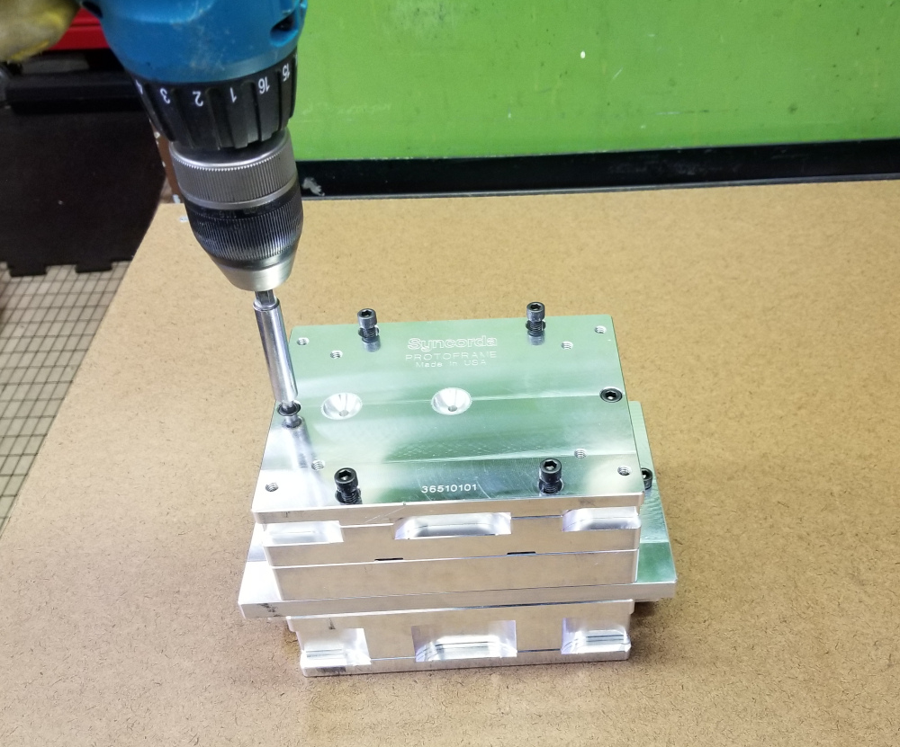
Figure 9 - Loosening clamp bolts
We open the mold using two screwdrivers in the pry slots.
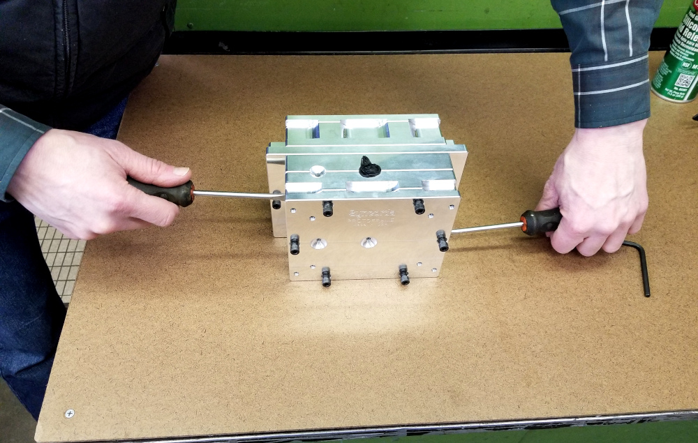
Figure 10 - Opening the mold
Step 5 - Ejecting the part
If everything worked properly, we will now have a part stuck in the B/core side of the mold. Time to use the ejection system.
We move the ejector plate forward toward the center of the mold to actuate the ejector pins. The wide ejector plate shown here makes it a bit easier to eject parts by hand. With an aluminum mold insert, it is frequently possible to eject the part just by squeezing the ejector plate to the B end plate by hand. 3D printed mold inserts have ridges between layers and the part can be very stuck to the core. We use the ejector bolts in the wide ejector plate to pull the ejector plate. We alternate tightening one side then the other so that both sides move forward evenly.
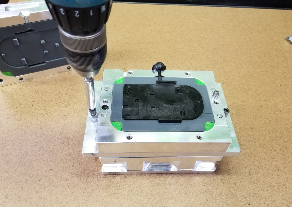
Figure 11 - Ejecting the part
The part is now just resting on the ejector pins.
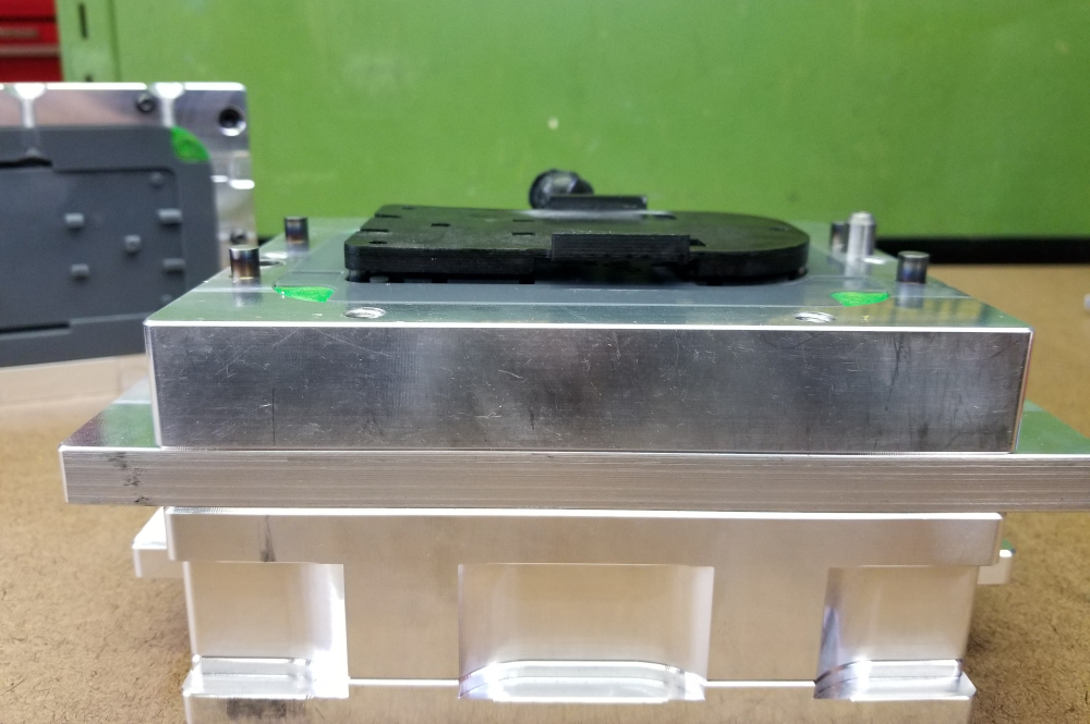
Figure 11 - The part now free from the mold
The Final Result
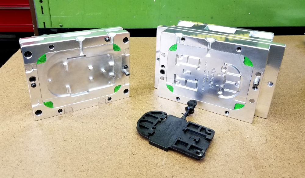
Here is the part after removing the sprue, shown next to the mold.

Figure12 - The result
For the mold shown above in this series, we were just using a 3D printed insert to test the part functionality and the mold design. With an aluminum mold insert and ejection system, this mold can run in an automatic injection molding machine. Here is the same mold with aluminum inserts that we machined after testing the 3D printed version.