Mold Ejector Setup: Part 1 - Adding part ejection to a prototype injection mold


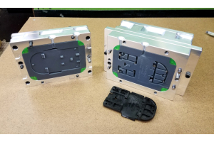
On a simple injection mold with shallow features, it is often possible to extract parts manually by pulling on the part, or using a screwdriver or chisel to pry an edge out. When parts start to get more complicated or have deeper features though, it can be challenging to extract them without damaging the part or the mold. Not only is prying parts out of a mold time consuming, prototype molds that are 3D printed or made from aluminum are very easy to damage with steel tools. The solution is to add an ejection system. In this post we will show the process of setting up an ejection system with a 3D printed mold insert installed in a Syncorda Protoframe mold frame.
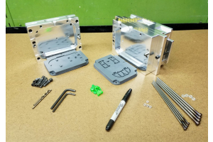
Tools
- Drill press
- Handheld drill
- Drill bits sized for ejector pins
- Abrasive cutoff saw or angle grinder with cutoff wheel
- Bench grinder
- Fine tip marker or layout stain for marking ejector pins
- V-Block with clamp or threaded 1-2-3 block with bolt
- Vernier caliper
- PPE - hearing and eye protection
The holes for the ejector pins need to be drilled straight so that the pins do not bind when the ejector plate is moved. While it might be possible to use a handheld drill, results will be much better with a drill press. We used an abrasive cutoff saw to cut ejector pins, but an angle grinder with a cutoff wheel would also work. You will need some way to hold the ejector pins while they are cut. This can be a v-block with clamp, a 1-2-3 block with a bolt threaded into it, or a bench vise if you are using an angle grinder to cut pins.
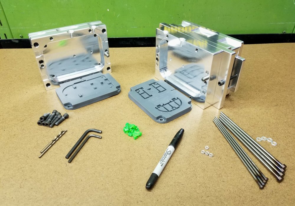
Materials
- Mold inserts (3D printed or machined)
- Mold frame with ejector hardware
- Ejector pins
- Ejector pin spacers (for pins 1/4" diameter and smaller)
- Wood block for backing plates when drilling
If you are using resin 3D printed mold inserts, you will want to print an extra B/core insert (the side with ejector pins). The aluminum swarf from drilling the ejector pin holes through the B end of the mold frame will enlarge the holes in the resin. After drilling the holes through the aluminum mold frame, it is preferable to have a new mold insert to install.
Mold Insert Design
You will first need to decide where to put the ejector pins in your mold. I am sure that much could be written about designing an optimal ejection system, but I will just go over a few basic points here.
You will want to put ejector pins in the half of the mold the part naturally sticks in when the mold is opened. If there is an obvious core and cavity, the ejector pins typically go on the core side. The plastic shrinks over the core as it cools, causing the part to stick to the core when the mold is opened. If this is a new design, you might want to try making a few parts without any ejection to see which half of the mold the part sticks in.
Once you know which half of the mold will have ejector pins, the next step is to decide on pin placement. The pins will leave very noticeable marks on the part, so choosing non-cosmetic locations is desirable. Ejector pins on ribs are common, in part due to the fact that pin marks on ribs are less noticeable than on larger flat surfaces. Pins should be placed somewhat evenly over the entire part so that the whole part is ejected at once and does not bend or deform during ejection. For part ejection, more pins are better, and larger pins are better. This must be balanced against part cosmetics though, where fewer pins and smaller pins are better.
You will probably want to add appropriately sized ejector pin holes to the model for your mold insert, and print 2 new core side mold inserts with the holes. Alternatively, you can also just drill holes through an existing mold insert, but printing the insert with holes for ejector pins provides more precise placement. You can use the holes in the insert as a drilling template.
Step 1 - Preparing to Drill
First, unbolt and remove the bottom clamp plate from the mold frame.
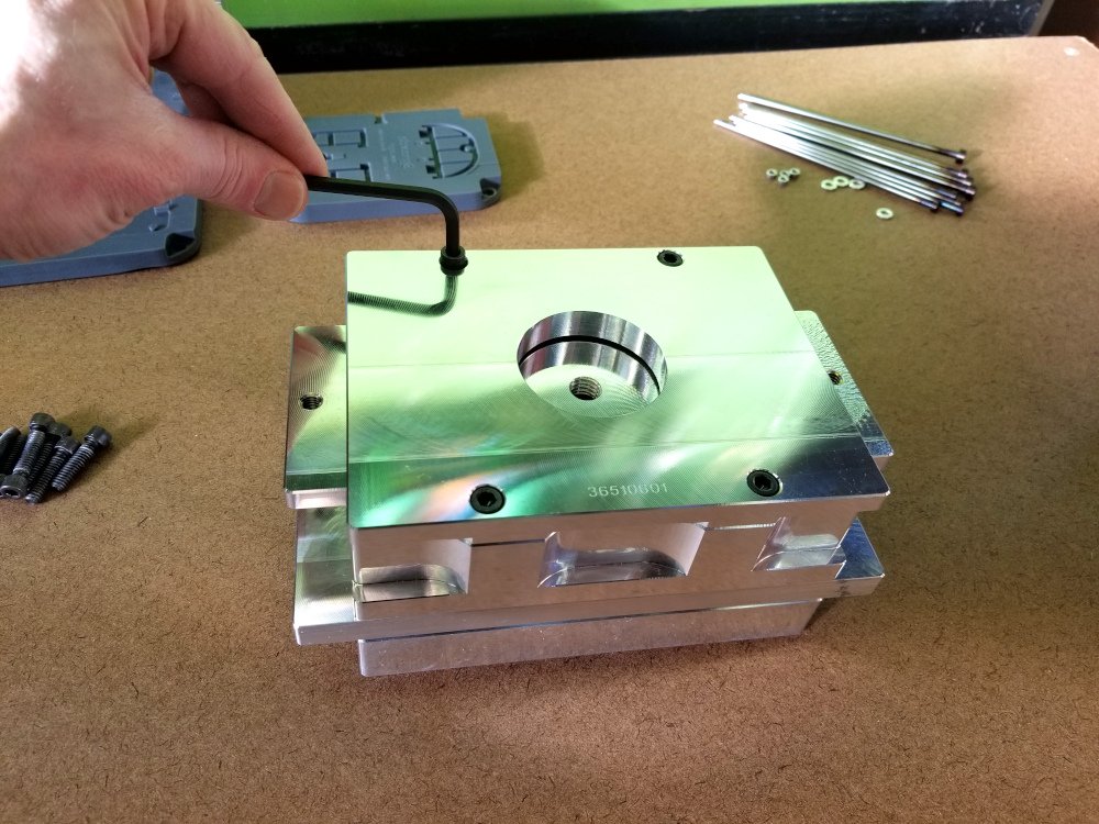
Figure 1 - Removing bottom clamp plate
Next, unbolt the ejector plate from the pin retainer plate and remove the ejector plate.
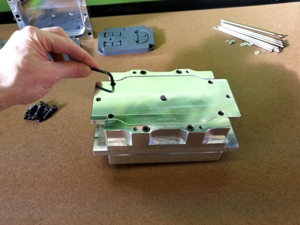
Figure 2 - Removing ejector plate
Cut a wood block to fit between the ejector risers. The block should be long enough to cover the heads of all 4 return pins in the mold frame, and tall enough to stick up above the aluminum riser blocks. This block will provide backing to drill through the B end plate and pin retainer plate of the mold frame.
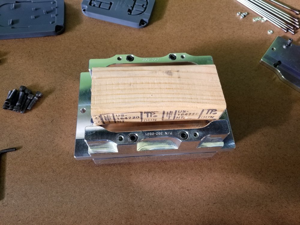
Figure 3 - Wood block for support when drilling
Install the mold insert in the B/Core half of the mold frame. The mold insert will be used as a template for drilling.
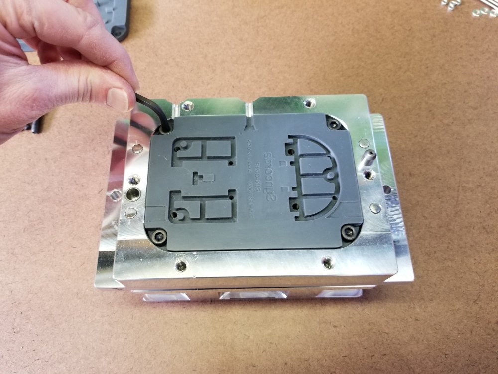
Figure 4 - Installing mold insert for drilling
Step 2 - Drill Ejector Pin Holes
Using the proper size drill bit chucked in the drill press, drill through the mold insert until it just makes a depression in the aluminum B end of the mold frame (spot drill). Repeat for each hole of the same size. If using multiple sizes of ejector pins, change the drill bit and repeat the process for each size.
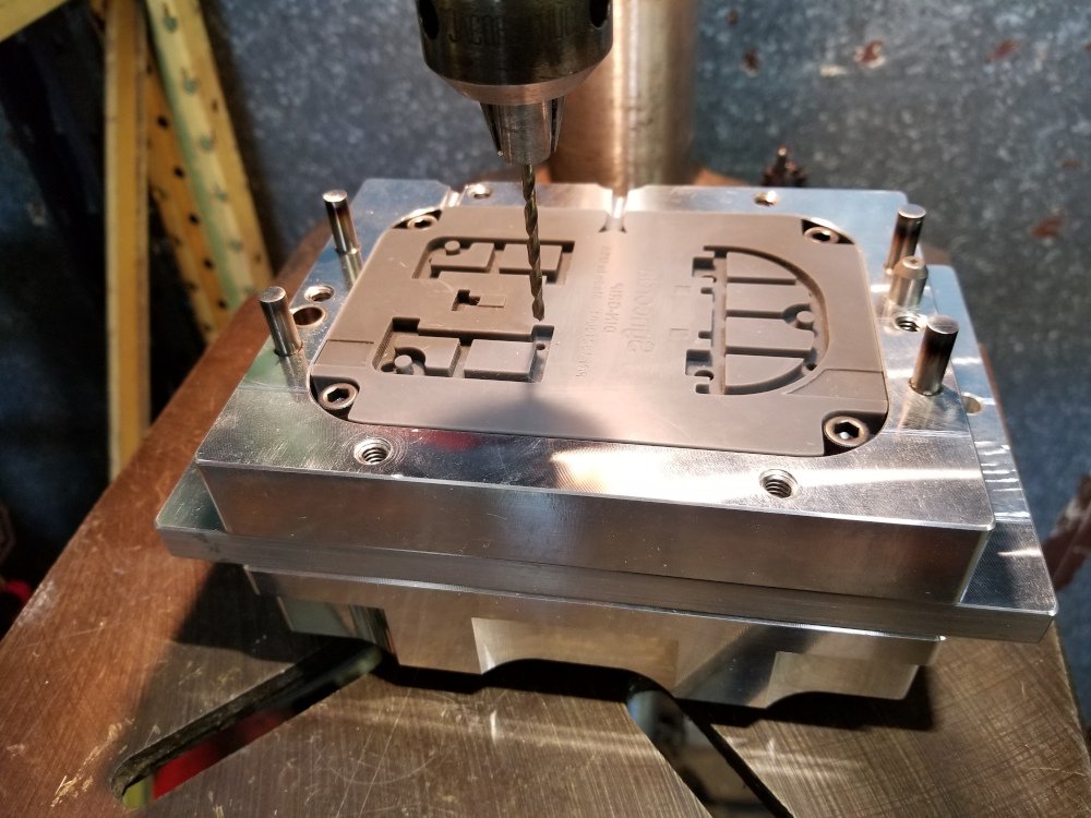
Figure 5 - Spot drilling B end plate through mold insert
Remove the mold insert. You should now have a hole started for each ejector pin. Place the mold frame on top of the wood block that you cut, so that it is resting on the heads of the return pins. With the appropriate size drill bit in the drill press, drill each hole completely through the B end plate and pin retainer plates. Cutting oil or WD-40 is recommended.
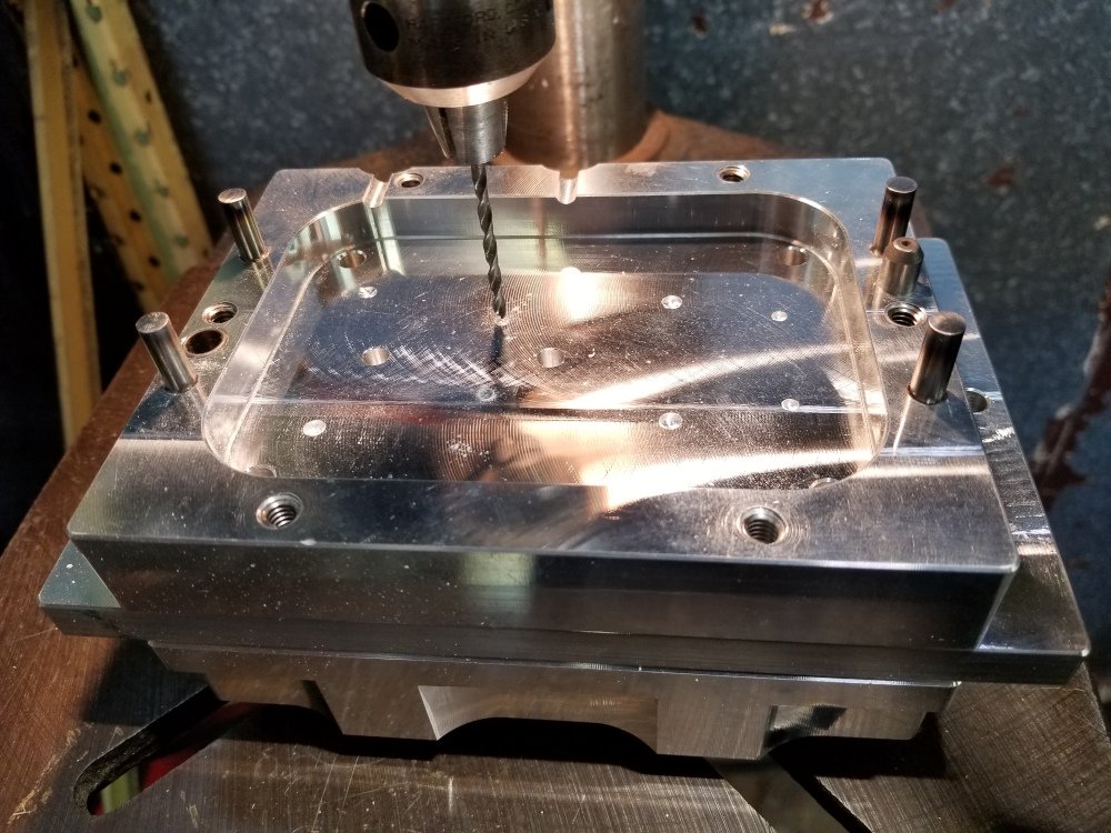
Figure 6 - Drilling through B end plate and pin retainer
Deburr any of the holes in the B end plate or ejector pin retainer plate as necessary.
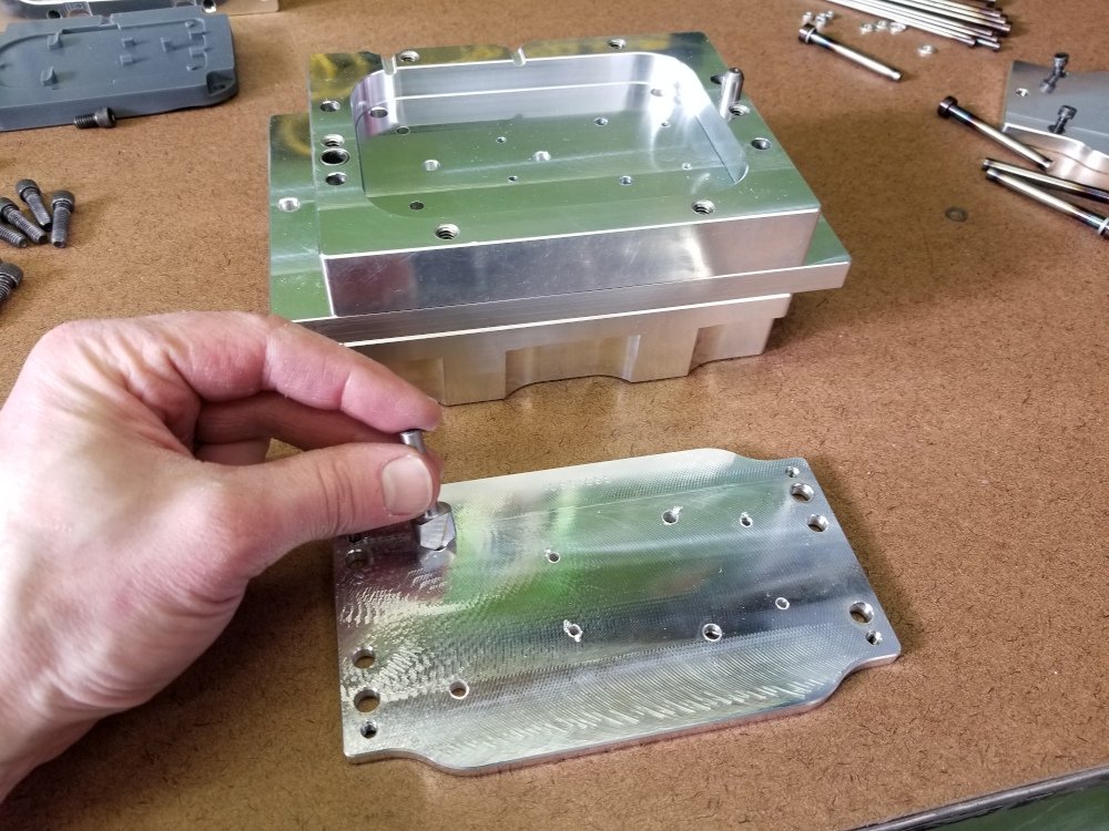
Figure 7 - Deburr as necessary
Step 3 - Test Fit Ejector Pins
Install the insert in the mold frame again.
Slide the proper spacer onto the first ejector pin. The spacer will bring the thickness of the pin head up to ¼” so that the heads of all pins are the same thickness.
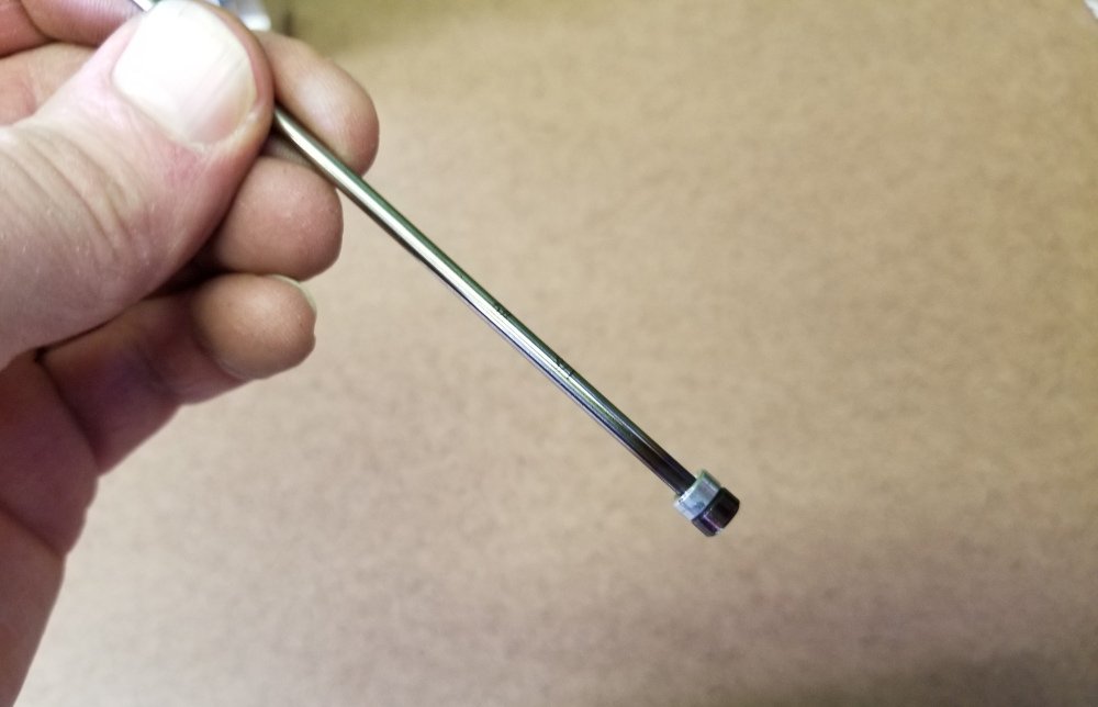
Figure 7 - Ejector Pin Spacer
Push the ejector pin through the pin retainer plate and into the appropriate hole in the mold
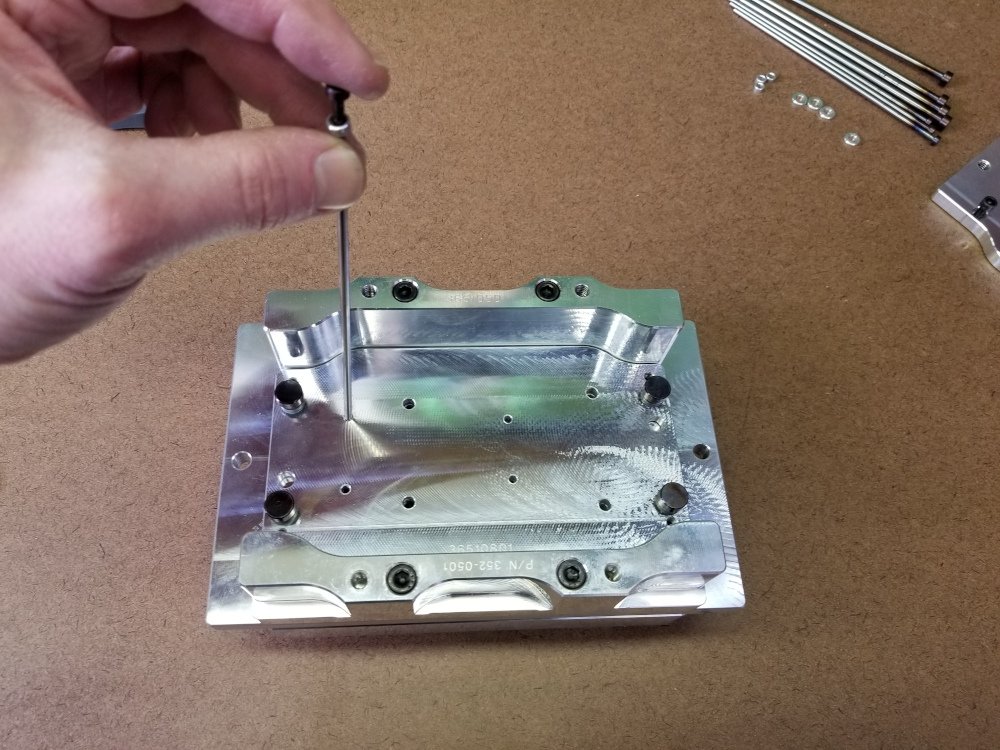
Figure 8 - Installing pin in mold
You will probably need to re-drill the hole to get the pin to slide through without binding. You can drill from the back side using the proper sized drill bit in a hand drill or drill press. A reamer is a better option if you happen to have one of the correct size. The hole should be a tight fit, but the pin needs to be able to move freely otherwise the ejector will be difficult to actuate by hand.
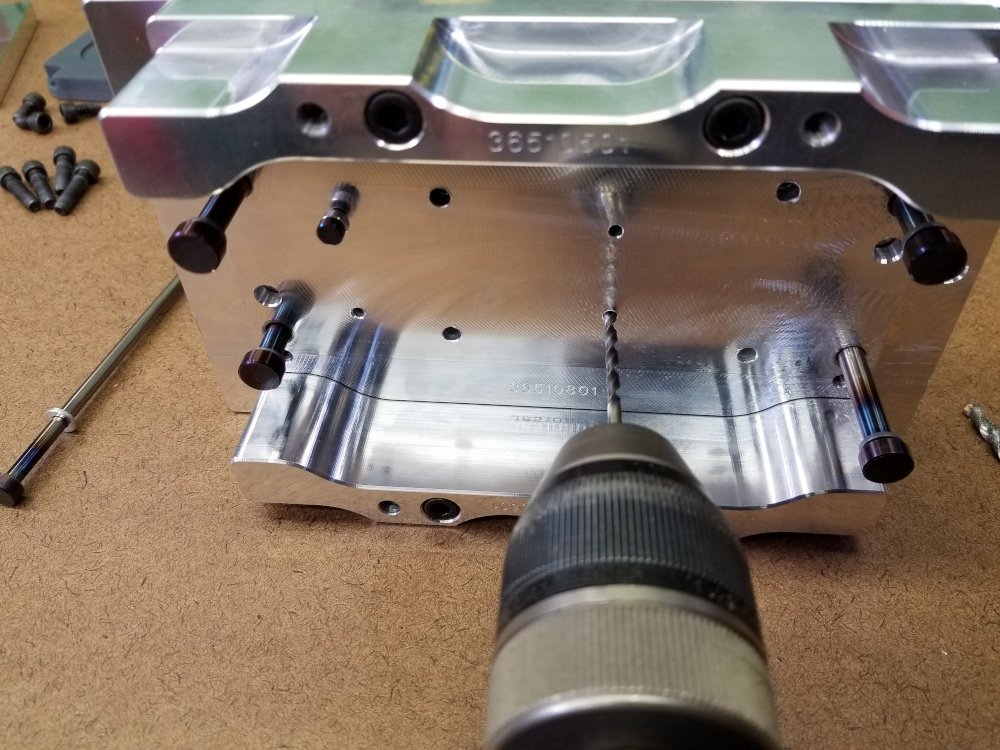
Figure 9 - Re-drilling pin hole
Repeat for each ejector pin. Leave each pin installed as you move to the next.
Step 4 - Determine Pin Lengths
This step will be easier if the ends of all ejector pins are in the same plane and therefore the pins are the same length. You can calculate the correct theoretical pin length using dimensions from your model and the drawing of the mold frame. In this post we will do it by marking the pins and iteratively test fitting.
Install the ejector plate.
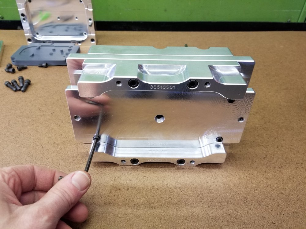
Figure 10 - Installing ejector plate
Install the bottom clamp plate
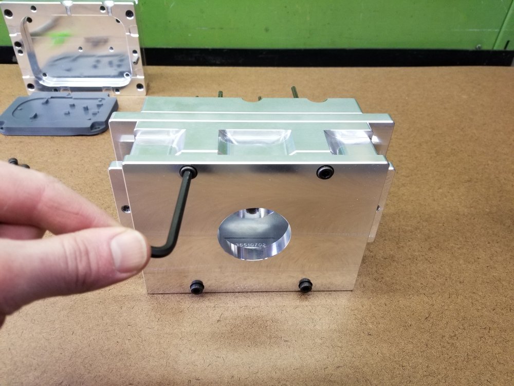
Figure 11 - Installing bottom clamp plate
Retract the ejector assembly until the ejector plate touches the bottom clamp plate.
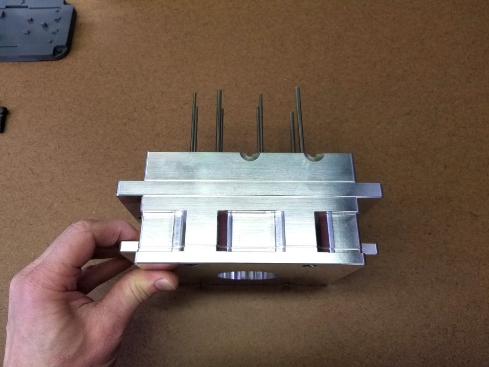
Figure 12 - Retracted ejector plate
Using a fine-tip marker, mark each pin as close as possible to where it should be cut. Layout stain (machinist’s blue) might work better here, but I have not had a chance to try it.
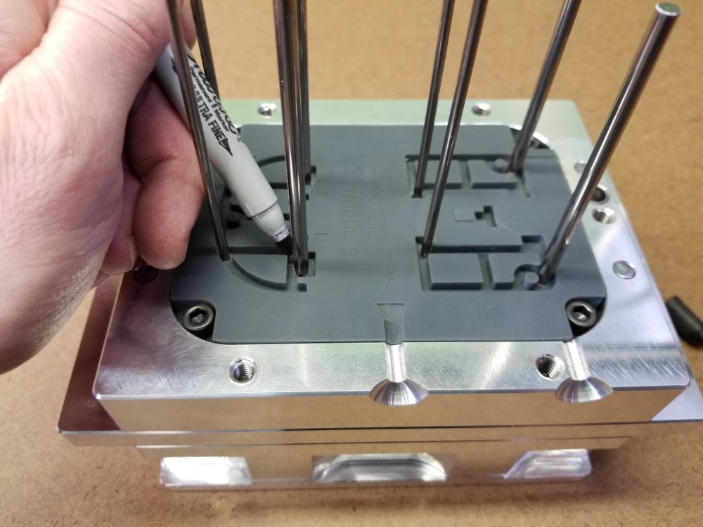
Figure 13 - Marking ejector pins
Remove the bottom clamp plate, ejector plate, and ejector pins.
On one of the pins, measure the length from the head of the pin to just below the mark using calipers. Record the length. Repeat for any pins that will be cut to be a different length.
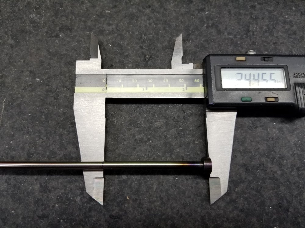
Figure 14 - Measuring pin length
Step 5 - Cut Ejector Pins
Using an abrasive saw or angle grinder with cutoff wheel, cut pins roughly to length. Cut just slightly longer than the final length to leave material for grinding to the exact length.
In the photo below we are holding pins in a 1-2-3 block that has threaded holes. A bolt is tightened on top of each pin to hold it in place for cutting. The block is then clamped in the abrasive saw. Another way to do this would be hold each pin in a V-block with a clamp.
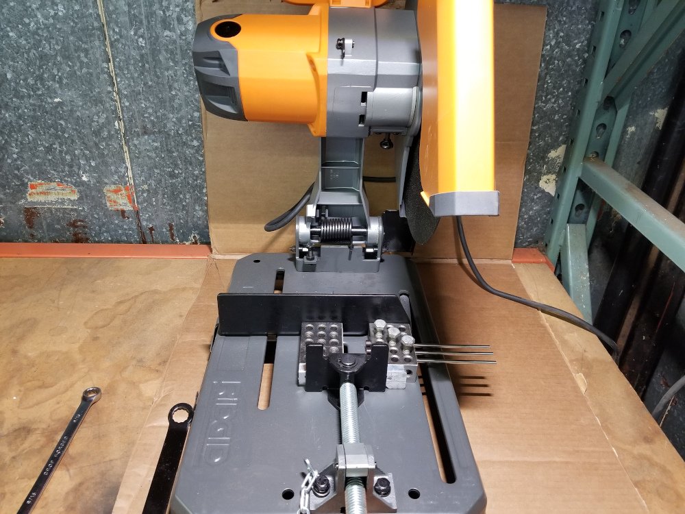
Figure 15 - Cutting ejector pins
The next step is to grind pins to the final length. The best way to do this is probably with a surface grinder, but since small R&D and home shops may not have a surface grinder, we are doing it with a standard bench grinder.
If the marks on your pins are no longer visible, you may want to mark them again to aid in rough grinding.
Start with one ejector pin. Set the caliper to a length just slightly longer than the desired pin length. Tighten the screw on the caliper to lock the jaw in place.
With a coarse grinding wheel, carefully grind a bit off the end of the pin while slowly turning the pin. Be sure to hold the pin perpendicular to surface of the grinding wheel as much as possible. Watch your fingers! Grinding wheels can rapidly take off skin too. If the pin starts getting too hot to hold, take a quick break.
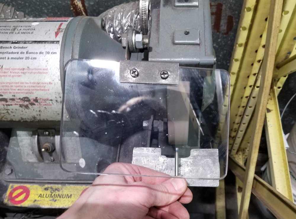
Figure 16 - Grinding ejector pin to final length
Test the length of the pin by trying to slide it between the jaws of the caliper. Continue grinding until the pin can just barely slide between the jaws.
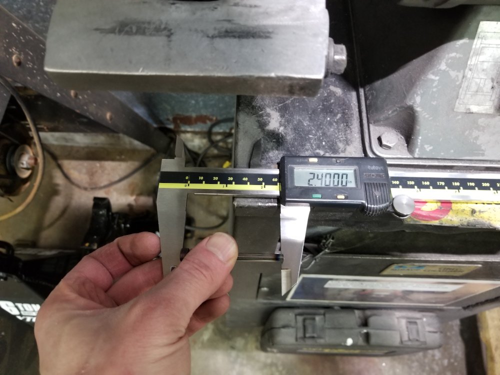
Figure 17 - Testing ejector pin length with caliper
Now, set the caliper to the final desired length and lock the jaw. Use a fine grinding wheel/green wheel to grind the pin to the final length. Rotate the pin slowly while grinding to grind evenly across the head. Grind until the pin can just slide between the jaws of the caliper. If you have a surface plate and height gauge, you can use that for this step rather than the calipers to be a bit more accurate.
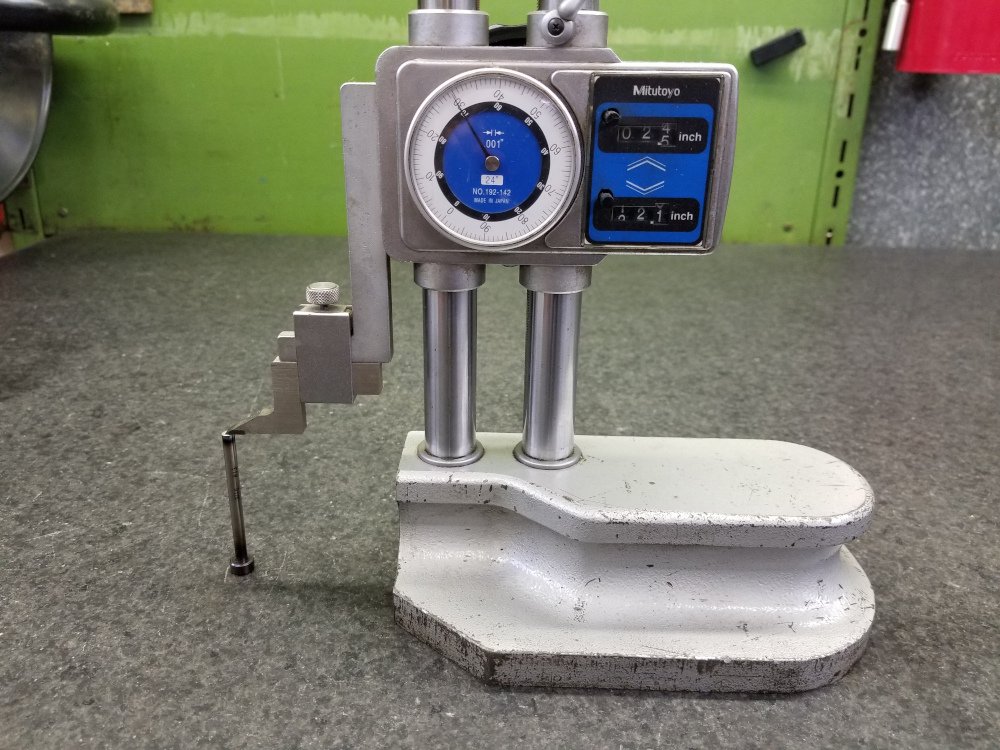
Figure 18 - Testing ejector pin length with height gauge (optional)
Test fit the pin in your mold to see if the height is acceptable. Adjust the desired pin length accordingly. Once the pin fits properly, grind the rest of the pins to the final length.
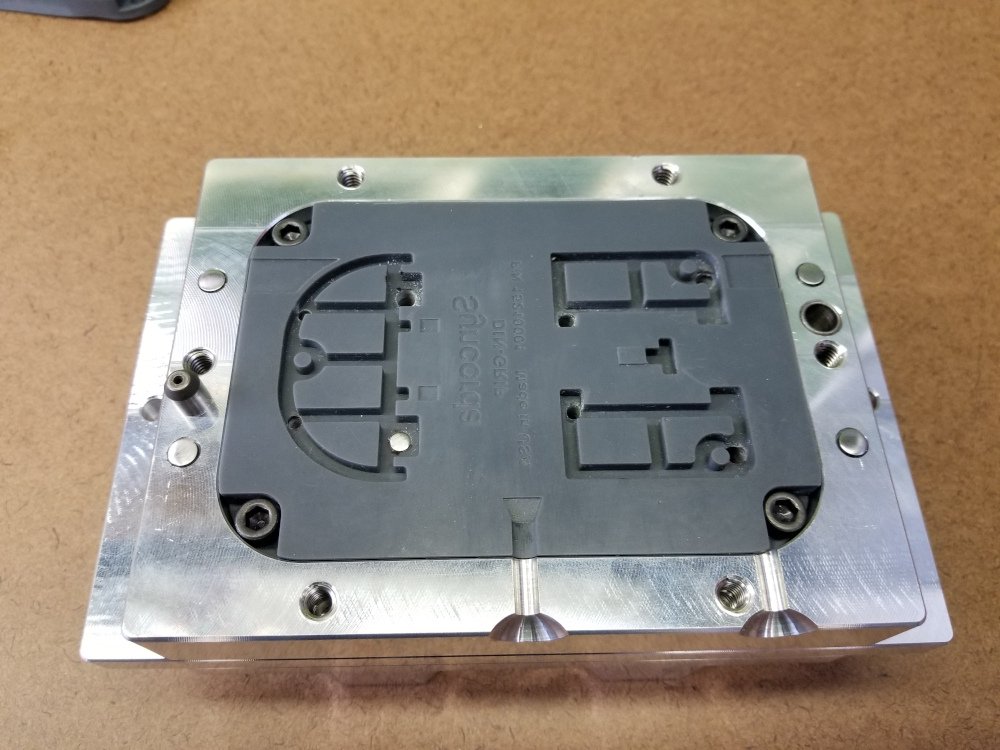
Figure 19 - Test fitting ejector pin in mold
With the pin grinding technique in this post you will end up with a crown on the end of each ejector pin. This will make the pin marks more visible on the part, but hopefully will still be acceptable.
Step 6 - Final Mold Core Assembly
At this point, all ejector pins have been cut to the proper length. If you have a second insert for your B/core mold half that has not been used as a drilling template, install it now.
Install ejector pins one at a time. For each pin hole, use a drill bit or reamer from the back side of the mold frame to make sure the holes in this insert are the proper size. Apply a small amount of grease to the ejector pin and install it. Be sure that the pin slides with minimal force, then leave it installed and move to the next pin.
Install the ejector plate and tighten the 4 bolts securing it to the pin retainer plate.
Install the bottom clamp plate and tighten the 4 bolts securing it to the risers.
The ejector plate should now be able to move back and forth to actuate the ejector pins.
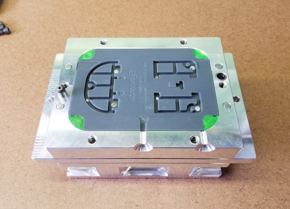
Figure 20 - The assembled mold core half
To see the mold in use, check out part 2 of this series.